

Galaxy Expand - Initial Configuration
Setting up the IP addressing for devices connecting to the backplane of the Galaxy Expand system requires planning.
In most instances, the backplane address space will be shared only by telephony devices, so there are few restrictions on the actual addresses used; they must confirm to standard internet addressing limits and they must not conflict with other addressing used in the system (i.e. the other UCX ethernet interfaces and the E-MetroTel VPN). While there are multiple methods for configuring the system to share a common subnet on the backplane interfaces, the following offers a simple method.
This section assumes that the UCX server card has been properly updated, activated, licensed, and configured for internet access on the customer LAN prior to beginning to add the other cards into the chassis.
Step ONE: Configure IP Address(es) on your laptop ethernet port
Windows machines can typically be configured to have multiple IP addresses assigned to a single ethernet interface. The IP addresses you configure will be dependent on which UCX server card you are using. (You can also configure all the addresses below on your laptop if you will be installing multiple Galaxy Expand systems in various configurations.) The exact address you assign can vary based upon your particular network configuration. The following example uses a ".199" address for each of the subnets.
The following table shows the IP addresses that can be used to connect to the various ethernet interfaces and devices on a Galaxy Expand system. You may not use all the configured subnets, but having them all pre-assigned on your laptop's ethernet interface can potentially assist in troubleshooting connectivity issues. It may be useful to refer to the connectivity diagrams shown in Galaxy Expand - Standalone UCx Server Configuration.
| IP Address | Subnet Mask | 2930 Server Card Application | i5 Server Card Application |
|---|---|---|---|
| 192.168.1.199 | 255.255.255.0 |
Enables laptop to connect to UCX backplane ethernet subnet via either ETH1 or ETH2 switch ports on the SFS card
Server Address: 192.168.1.200
|
Enables laptop to connect to:
Server Address: 192.168.1.200 |
| 192.168.10.199 | 255.255.255.0 |
Enables laptop to connect to UCX via the ETH port (Ethernet 1) on front of 2930 Server card
Server Address: 192.168.1 |
Enables laptop to connect to:
|
| 192.168.11.199 | 255.255.255.0 | not used on 2930 Server card |
Enables laptop to connect to:
Server Address: 192.168.11.200 |
| 172.16.99.199 | 255.255.0.0 |
Can be used to connect to individual FXS 16-port for management using the Reserved Address IP based on the Galaxy Expand slot addressing (see diagram below) by connecting to either of the Ethernet switch ports on the SFS card. Server Address: none |
|
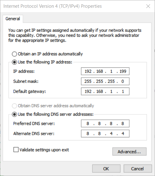
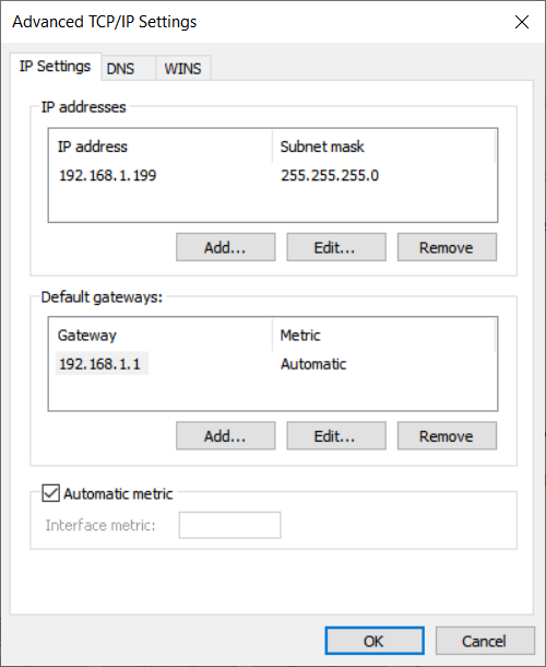
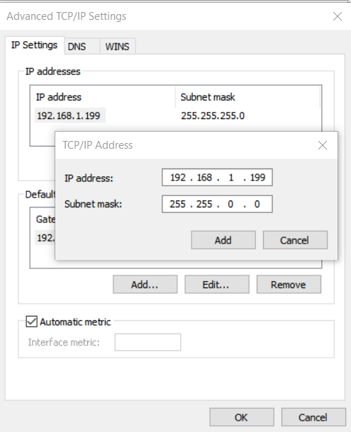
To configure multiple IP Addresses on a Windows device, edit the properties of the Internet Protocol Version 4 (TCP /IPv4) configuration of the Ethernet connection in the systems settings, and use the Advanced button to add additional addresses and subnet masks according to the table above. Click the Add button in the Advanced TCP/IP Settings screen, enter one of the additional IP addresses, verify the calculated subnet mask, then click Add.
Step TWO: Configure the DHCP Server on the UCX
Make sure that the server card is installed in slot 7a/b of the Galaxy Expand and no DSM16p, FXS 16-port, or PRI cards are installed in the chassis.
If you have multiple chassis, connect one of the ethernet ports (ETH1 or ETH2) on the SFS card in one chassis to an ethernet port on the SFS card in the second chassis.
- Navigate to the System / Network page in the UCX Web based Configuration Utility.
- In the Network Parameters page, set the IP address of the backplane ethernet interface to the value you plan to to use for actual deployment. For the 2930 Server Card and the i5 Server Card v2, the backplane uses Ethernet 0 while the i5 Server Card (original or v1) uses Ethernet 2.
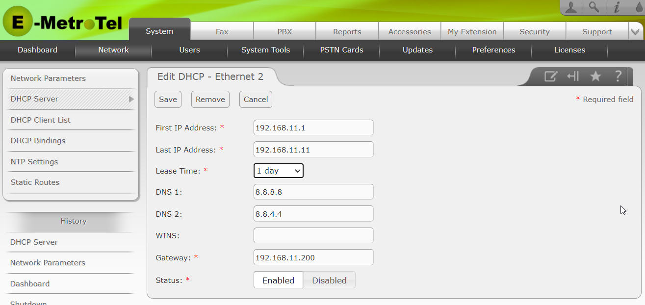
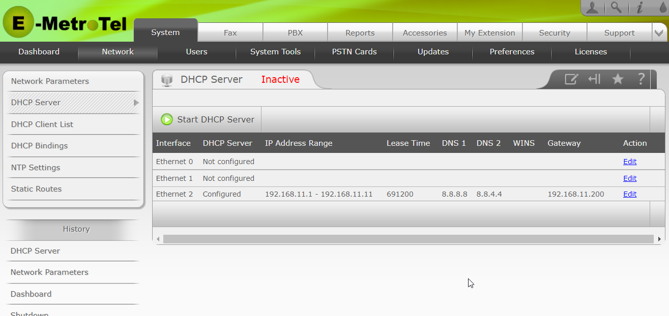
- In the DHCP Server page, click Edit on the line corresponding to the backplane ethernet interface for your system.
- Set the First IP Address and Last IP Address to a valid range for that ethernet subnet that would cover the number of expected ethernet based telephony interface cards. For example, if you have an i5 Server Card v1, set the first IP Address to be 192.168.11.1 and the Last IP Address to be 192.168.11.11. (If you have more than one local Galaxy Expand shelf you may want to configure a higher Last IP Address.)
- Set the DNS 1 and DNS 2 values to valid DNS server addresses such as 8.8.8.8 and 8.8.4.4.
- Set the Gateway address to be the IP address of the UCX Server Card interface that is able to communicate with the internet.
- Set the Status to Enabled.
- Click on Save.
The following is an example DHCP configuration for Ethernet 2 of an i5 Server Card with a single Galaxy Expand chassis:
Once you have saved the DHCP Server settings for the backplane ethernet, make sure that the DHCP Server is only configured for the backplane Ethernet interface unless otherwise required for your deployment. The DCHP Server should indicate Not configured for the other interface(s). If needed, disable the unwanted settings by clicking on the Edit button for that interface, clicking Disable and then clicking Save..
Then click on Start DHCP Server.
You will now see the DHCP Server status for the backplane (Ethernet 2 for i5 Server) as Active.
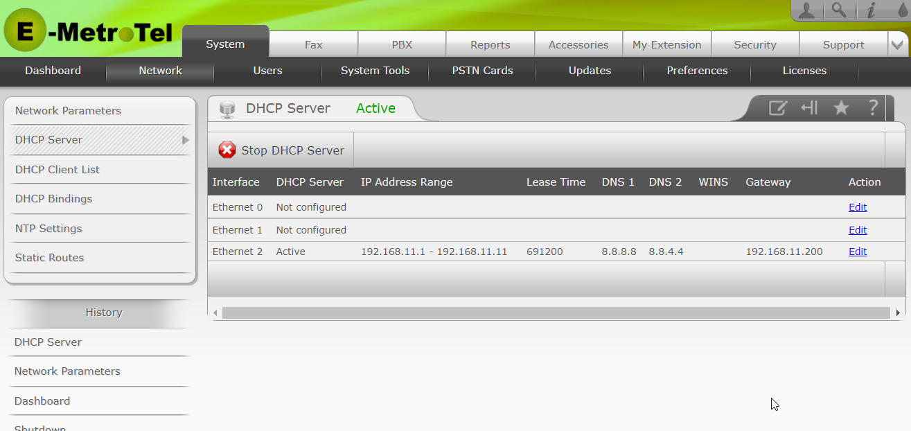
Note that DHCP should be used only for establishing the initial connection to any of the telephony interface cars on the chassis backplane. Once cards are online, they should be reconfigured to Static addresses, and the DHCP Server address range set to exclude the configured IP addresses (or disabled completely).
Step THREE: Install the cards in the Galaxy Expand
Make note of the MAC Address of each DSM16p, FXS 16-port, and PRI card and the slot it will be plugged into during Step FOUR, below. Firmly seat each of the DSM16p, FXS 16-port, PRI, FXS 8-port and FXO 8-port telephony interface cards into the desired slots on the Galaxy Expand shelf (or shelves).
As you insert the cards and they begin their boot process, you will notice the LED cluster on the Switch Fabric (SFS) card become active, with Red LEDs corresponding to ethernet connected cards (DSM16p, FXS 16-port, and PRI) and Green LEDs corresponding to DAHDI based cards (FXS 8-port and FXO 8-port). After a few minutes, the cards will be ready to configure.
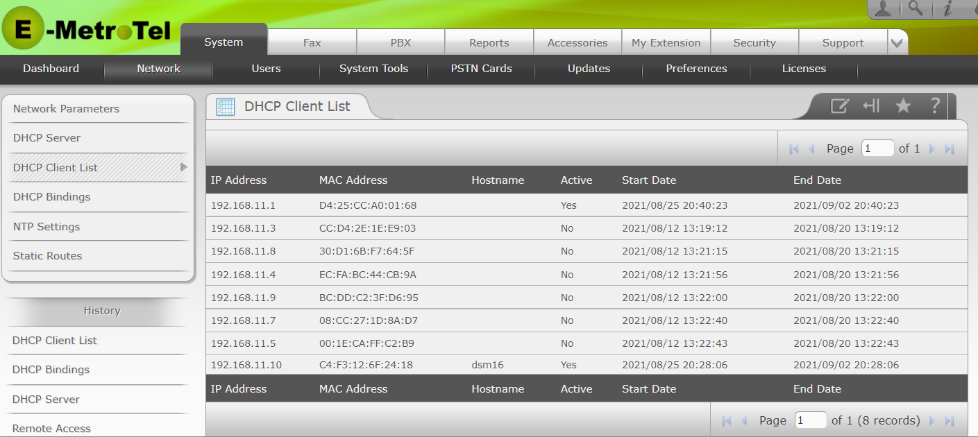
Step FOUR: Identify the IP Addresses associated with each IP-enabled card
All of the cards will by default attempt to obtain an IP address using DHCP during the start-up phase of the card. To learn the address of each card, review the DHCP Client List by navigating to the System / Network / DHCP Client List page and matching the IP Address to each MAC address noted in the previous step.
Step FIVE: Add devices on UCX Backplane to the Do Not Block list
Typcially the only devices connecting to the UCX backplane ethernet interface are telephony related devices. The IP Addresses associated with these devices, particularly any devices that will be sending password related information or call setup requests should be configured as Do Not Block addresses for the Telephony component of the Monitored Services in the IP Block List functionality of the UCX, Failing to do so may impact the ability for one or more Gallaxy Expand modules and/or SIP devices to connect to the UCX, as a series of failed connection attempts from any of the device IP addresses will caused those addresses to be blocked. For example, a single extension with a mis-configured SIP sectret (password) will result in all 16 extensions on that card to be blocked. Depending on the elvel of security required, you may enter individual addresses or the entire subnet to the Telephony Services Do Not Block list.
Step SIX: Set up Connection Sharing on the Server Card
Follow the instructions described in Network Parameters to set up Connection Sharing making sure the the backplane interface of the server card (Ethernet 0 for 2930 Server Card and Ethernet 2 of the i5 Server Card) is selected as the Private Interface. This will allow the DSM16p devices to communicate with E-MetroTel during the Activation phase as well as to receive software updates from E-MetroTel servers.
Step SEVEN: Configure Remote Hosts for each ethernet based card
In order to be able to communicate with each card connected on the Galaxy Expand backplane subnet when you do not have direct access to the SFS ethernet ports, you must configure Remote Host settings for the IP address associated with each card. The process for configuring Remote Hosts is described in UCX Remote Access.
The ports you are required to specifiy for the Remote Host settings vary for each type of ethernet-connected Galaxy card
| Type of Card | Recommended Ports |
| DSM16p | 443 (https), 22 (SSH) |
| FXS 16-port | 443 (https), 80 (http), 12345 (SSH) |
| PRI Card | 443 (https), 80 (http), 12345 (SSH) |
Step EIGHT: Connect to each individual card
Having identified the addresses of each of the cards in your system and set up Remote Host connections for each of them, you can now follow the standard procedures for activating, updating and configuring of the telephony related functionality. If you are not directly connected to the backplane ethernet through the SFS card, you will need to click the Connect button beside each Remote Host entry before you can connect to the card through the browser.
DSM16
Follow the UCX Digital Station Module (DSM16) documentation.
- Connect to the card(s) by clicking on the active Remote Host https port link for each card.
- Ensure that the Default Gateway in the Ethernet 0 settings in System Network / Network Parameters points to the UCX server card's backplane IP address and that a valid DNS server is defined. Change the Interface Type to Static.
- Activate the system
- Configure the NTP Server and Preferences to ensure the system clock is accurate and that the local time zone is being used.
- Configure the Gateway IP Address to allow the digital sets to communicate to the Server card.
- Configure any other Gateway related settings (Digital Set type, etc.) required for your customer.
FXS 16-port
Follow the Galaxy FXS 16-port Card documentation.
- Connect to the card(s) by clicking on the active Remote Host http port link for each card.
PRI Card
Follow the Galaxy PRI-1 Card documentation.
- Connect to the card(s) by clicking on the active Remote Host http port link for each card.
FXS 8-port and FXO 8-port Cards
These cards are recognized directly by the UCX software on the server card and appear as Installed Cards in the System / PSTN Cards page ot the Web-based Configuration Utility. Refer to Installed Cards - Analog Hardware for additional information on setting the hardware parameters and to Adding a DAHDI Extension and Adding DAHDI Trunks for how to configure the telephony aspects of these cards.