

Install an Interface card in the UCx1000E
Step One: Getting the UCx1000E ready for card installation
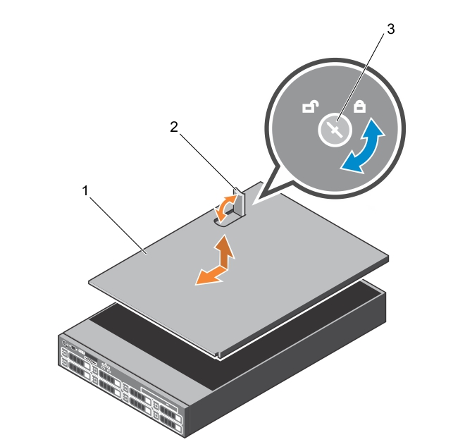
- system cover
- latch
- latch release lock
Step Two: Determining and Identifying the Card Slot
The following table lists the supported expansion card types and slots.
| Riser | Card slot | Processor connection | Height | Length |
|---|---|---|---|---|
| 1 | 1 | Processor 2 | Half Height | Half Length |
| 1 | 2 | Processor 2 | Half Height | Half Length |
| 1 | 3 | Processor 2 | Half Height | Half Length |
| 2 | 4 | Processor 2 | Full Height | Full Length |
| 2 | 5 | Processor 1 | Full Height | Full Length |
| 3 (default) | 6 | Processor 1 | Full Height | Full Length |
| 3 (alternate) | 6 | Processor 1 | Full Height | Full Length |
| 3 (default) | 7 | Processor 1 | Full Height | Full Length |
Riser 1 Card Slots
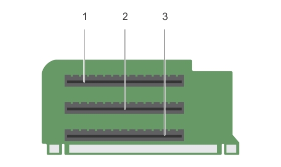
- card slot 1
- card slot 2
- card slot 3
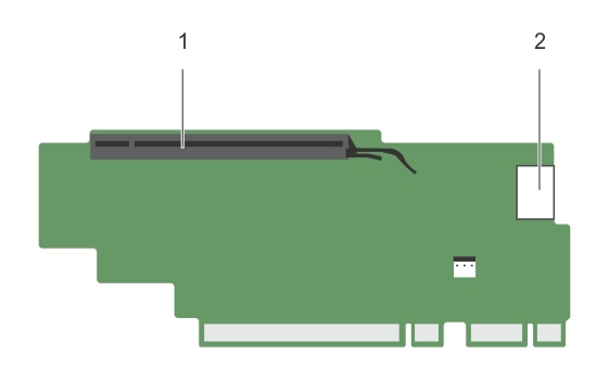
Riser 2 Card Slots
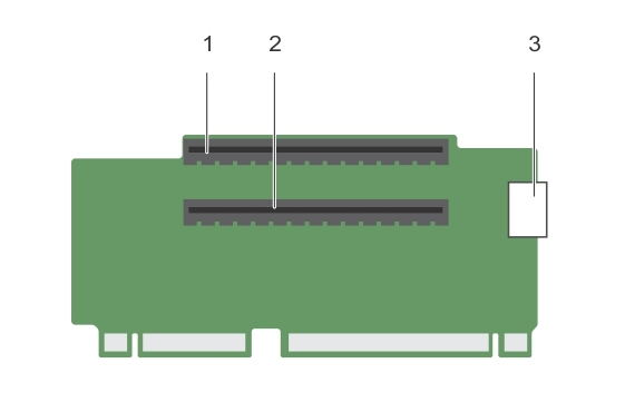
- card slot 4
- card slot 5
- power connector
Riser 3 Card Slots
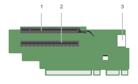
- card slot 6
- card slot 7
- power connector
Riser 3 (alternate) Card Slots
- card slot 6
- power connector
Step Three: Installing the Interface (expansion) card
Installing interface card on Riser 2 or 3
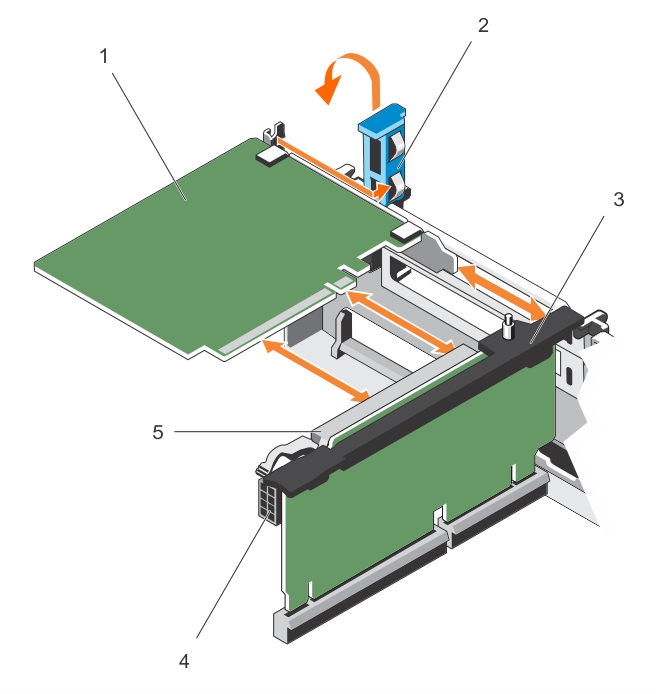
- expansion card
- expansion card latch
- expansion card riser
- power connector
- expansion card connector
Installing interface card on riser 1
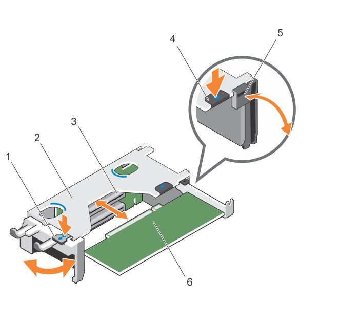
- tab A
- expansion card riser 1 cage
- expansion card connector
- tab B
- latch
- expansion card
Figure 4: Removing and installing expansion card riser 1
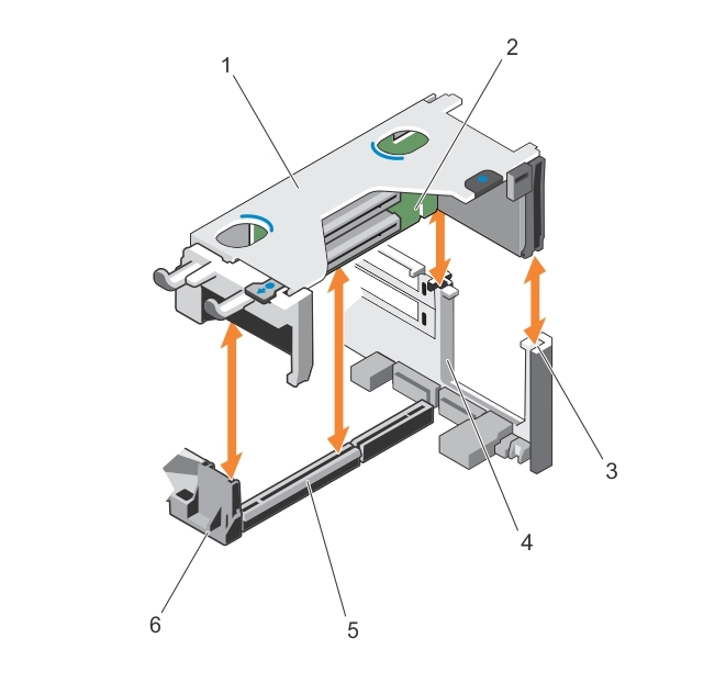
- expansion card riser 1 cage
- expansion card riser 1
- riser guide-back (right)
- riser guide-back (left)
- expansion card riser 1 connector
- riser guide-front
Step Four: Closing the System
- Align the slots of the system cover with the tabs on the chassis.
- Press the cover release latch, and push the cover toward the front of the chassis until the latch locks into place.
- Turn the latch release lock clockwise to the lock position.
- Reconnect the system to its electrical outlet and turn the system on, including any attached peripherals.
Once the UCX server is powered up, the new Interface Card will be automatically detected. See PSTN Cards in the Administration Guide for details.