

Galaxy PG1 Quick Installation Guide
Overview
E-Metrotel's Galaxy PG1 is a SIP to Paging and Video intercom device for use in various industry applications. The media stream transmission adopts standard IP/RTP/RTSP protocol, with the stability and sound quality of an IP phone. It has various functions and interfaces that include intercom, broadcast, video, security and recording. It can adapt to different application environments and is simple to install, making PG1 ideal for any business.
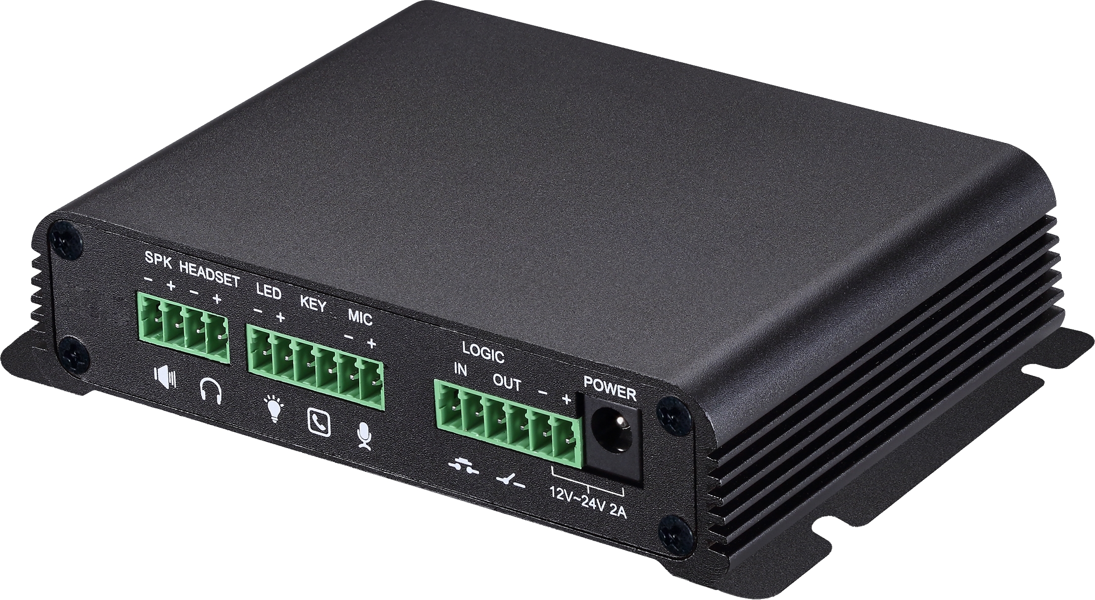
Table of Contents
1. Device Port Description
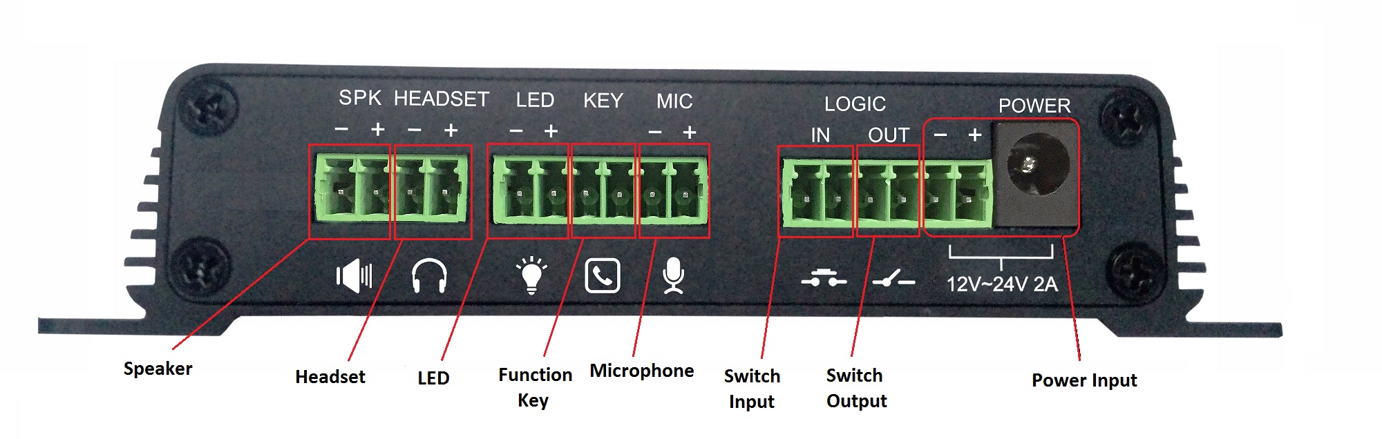
| Speaker | External Amplified Speaker ports. The input power adapter size needs to correspond to the output speaker wattage. See Set the Speaker Settings for further details. Recommend using 18 AWG gauge speaker wire. |
|---|---|
| Headset | External panel speaker or headset ports. |
| LED | External LED ports for registration, network and call status. |
| Function key | External Function key ports for connecting buttons or door bells etc. When engaged a phone number can be speed dialed. |
| Microphone | External Microphone ports. |
| Switch input | Security sensor ports. Example: Door sensor, infrared probe or an emergency switch. |
| Switch output | External ports for alarm lights, electric locks and other similar equipment. |
| Power input |
12V ~ 24V 2A input. The maximum output power amplifier is determined by the input voltage. The device supports PoE. Power adapter is not included. |
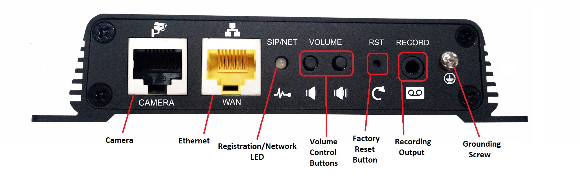
| Camera | Standard RJ45 interface for security camera. |
|---|---|
| Ethernet | 10M/100M ethernet WAN port. PoE supported |
| Registration / Network LED |
Indicates the network status, call status, registration status.
|
| Volume Control buttons |
Volume adjustments depending on state of the device.
Press and hold the volume down key to broadcast the IP address. |
| Factory reset button | Press and hold for 3 seconds to flash the device to restart and restore the factory settings. |
| Recording output | External ports for recording devices or computer mic input. |
| Grounding screw | Grounding screw for external devices to prevent static build and shock to system. |
2. Device Installation
Step One
Install device securely in desired location using the provided screw slots.
Step Two
Connect Speakers and other external equipment to the back of the unit as desired. It is recommended to attach a grounding cable.
Step Three
Plug the network cable to a PoE enabled switch, the device light flashes when the power connection is normal.
3. Discover IP address
There are 3 methods to find the IP address of the device.
Method One
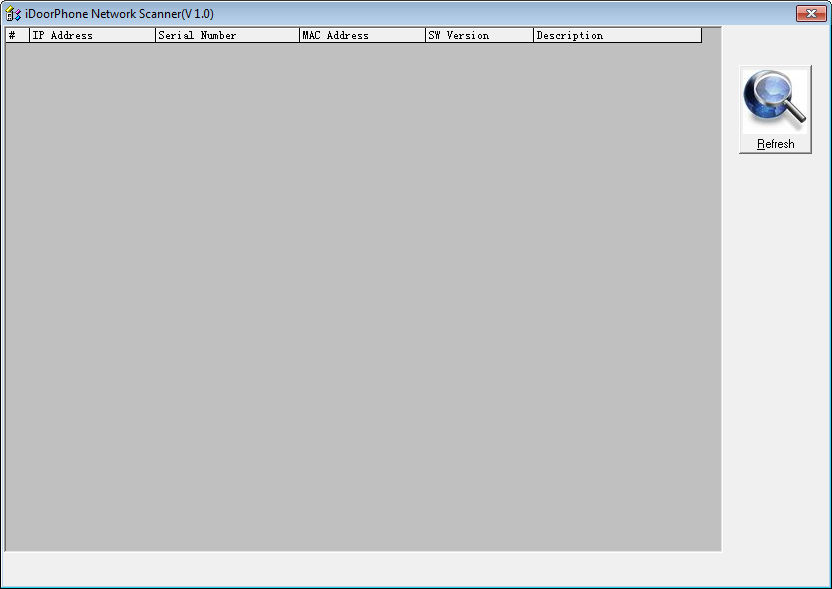
Download the simple Network Scanner tool from iDoorPhone: https://idoorphonenetworkscanner.software.informer.com/1.0/
Run the Network Scanner tool. Press the Refresh button to search the door phone and find the IP address of the E-MetroTel Galaxy PG1 device.
Method Two
Make sure speakers are connected to the device first, then press the volume down button for 3 seconds, the device will automatically voice broadcast the device's IP address.
Method Three
Make sure speakers are connected to the device first, then press and hold the volume up button for 10 seconds, when a rapid beep is played, quickly press the volume up button 3 times and the beep will stop. Wait 10 seconds. The device will switch switch to Dynamic IP and voice broadcast its IP address.
Repeating the above steps will toggle the network mode back to Static IP address.
4. Configure SIP account on UCx Server
- Open the UCx Web-based Configuration Utility
- From the PBX tab, select PBX Configuration
- From the left side column, select Extensions
- In the drop-down list box, select the device type Generic SIP Device and press the Submit button
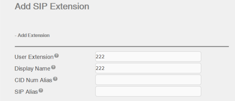
- Enter the extension number of the SIP extension in the User Extension field
- You must enter something in the Display Name field.
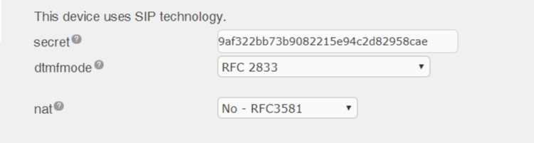
- In the Device Options section, you will need to enter a password in the Secret field.
- Press the Submit button at the bottom of the page.
- When done, click on the Apply Config bar.
5. Configure the PG1 Device
5.1. Access the Web Interface
Enter the IP address of the PG1 device from a browser window. The default IP address of the device is 192.168.1.128.
Login using the default root login credentials:
- Username = admin
- Password = admin
5.2. Add SIP account
Navigate to Line -> SIP page and perform the following steps:
- SIP Server Address field, enter IP address of UCx Server
- SIP Server Port field, enter the port number used by UCx Server (default 5060)
- Phone number, Display name, Authentication Name fields, enter the SIP extension configured on the UCx Server
- Authentication Password field, enter the secret/password of the SIP extension configured on the UCx Server
- Select the Activate checkbox
- Click the Apply button to save the settings
5.3. Set the Volume
Navigate to Intercom settings -> Audio page and adjust the volume levels of the following parameters:
- Speakerphone
- Broadcast Output Volume
- MIC Input Volume
- Singal Tone Volume
Click the Apply button to save the settings.
5.4 Set the Function Key
Navigate to Function Key page and configure the following:
DSS Key 1
- Type = Hot Key
- Number 1 = Enter the number to dial
- Number 2 = Enter the second number to dial if Number 1 is not available, or leave blank
- Line = Select a working line
- Subtype = Speed Dial
Click the Apply button to save the settings.
5.5 Set the Speaker Settings
The Speaker Settings default mode is Panel Speaker. Use this mode when connecting to a device that contains both speakers and microphone. Device cabling is connected to the Headset ports. The output power is limited to 10W.
If external loud speakers are used for broadcasting, it can be changed to External Speaker mode. Device cabling is connected to the Speaker ports.
Select the speaker audio output wattage: 10W / 20W / 30W, and they must match the corresponding power supply as indicated in the table below:
| Input Power | Audio output | Speaker Type |
|---|---|---|
| POE | 10W | 10W/4Ω |
| 12V/2A DC | 10W | 10W/4Ω |
| 18V/2A DC | 20W | 20W/4Ω |
| 24V/2A DC | 30W | 30W/4Ω |
5.6 Set the Camera
A security camera can either be connected directly to the unit or to the local network. It is recommended to use an external camera connected to the local network.
Perform the following steps to configure the device:
- Navigate to Intercom Settings -> Video page
- For Connect mode, select External and click Apply
-
Under IP Camera Settings, configure the following parameters:
- User - External camera login account username
- Password - External camera login account password
- IP Camera brand - Select the camera's manufacturer
- IP - IP address of the camera
- Click the Apply button
PG1 will automatically connect to the external camera and display the status.